· Mechanics of Materials · 6 min read
A Visual Guide to Mohr's Circle for Plane Stress Analysis
Explore stress transformation in materials with our FREE online Mohr’s Circle calculator and interactive 2D stress visualizer.
Try Mohr Circle Visualizer
Visualize stress transformations and principal stresses in real-time.
Imagine a tiny, almost invisible square element within a structural beam, a machine component, or even the ground beneath us. This element is constantly subjected to internal forces – pulls, pushes, and sliding actions. We collectively call this internal resistance to external forces stress. Understanding stress is fundamental in engineering mechanics and stress analysis.
In many 2D (plane stress) scenarios, we start by knowing the stresses acting on the faces of this element aligned with our standard x and y axes:
- Normal stress (perpendicular to the x-face)
- Normal stress (perpendicular to the y-face)
- Shear stress (parallel to the x-face, in the y-direction, and its counterpart on the y-face)

But what if we need to know the stresses on a plane tilted at an angle relative to our x-axis? Let the new axes aligned with this tilted plane be x’ and y’. The normal stress on the x’-face is denoted (or sometimes ), and the shear stress on the x’-face acting in the y’-direction is (or sometimes ). These stresses will generally be different from and . This is the core of stress transformation. When plotting on Mohr’s Circle, the point representing the stress state on the x’-face (Point X’) has coordinates .
To calculate these transformed stresses, engineers use the following stress transformation equations:
Although these equations provide exact solutions, their complexity can make it challenging to develop an intuitive understanding of stress transformation. Fortunately, Mohr’s Circle offers a brilliant graphical method that greatly simplifies plane stress analysis!
Mohr’s Circle: Simplifying Stress Transformation
In the late 19th century, German engineer Christian Otto Mohr developed a graphical technique called Mohr’s Circle. It elegantly visualizes the state of stress at a point and allows us to determine stresses on any plane, including principal stresses and maximum shear stress, by simple geometry.
Constructing Mohr’s Circle: A Step-by-Step Guide for Stress Analysis
Let’s build Mohr’s Circle for a given state of plane stress .
1. Establish the Coordinate System for Mohr’s Circle:
- The horizontal axis represents Normal Stress (). Positive (tensile) is to the right; negative (compressive) is to the left.
- The vertical axis represents Shear Stress (). This sign convention is crucial:
- Shear stress on an element face that tends to cause Counter-Clockwise (CCW) rotation of the element is plotted above the -axis (positive ).
- Shear stress that tends to cause Clockwise (CW) rotation is plotted below the -axis (negative ).

2. Plot Two Key Points (X and Y): We represent the stress state on the original x and y faces as two points on this plane:
- Point X: Represents the stress state on the face whose outward normal is the x-axis. Its coordinates are . The is because if the input is positive (defined as causing CW rotation on the x-face as in Fig 1), it’s plotted in the negative region of the circle.
- Point Y: Represents the stress state on the face whose outward normal is the y-axis. Its coordinates are . If input is positive (CW on x-face), then causes CCW rotation on the y-face, so it’s plotted in the positive region.
3. Locate the Center of Mohr’s Circle (C): The center of Mohr’s Circle always lies on the -axis. It represents the average normal stress: The coordinates of the center are .
4. Determine the Radius of Mohr’s Circle (R): The line segment connecting Point X and Point Y is a diameter of the circle. The radius can be found using the distance from the center C to either Point X or Point Y:
5. Draw Mohr’s Circle: Using the center and the calculated radius , draw the circle.

Interpreting Mohr’s Circle: Finding Principal Stresses and Max Shear
This single circle is packed with critical information for stress analysis:
- Any Point on the Circumference: Each point on the circle’s edge represents the normal stress and shear stress on a particular plane through the material.
- Angles on the Circle vs. Reality: A physical rotation of a plane by an angle (say, counter-clockwise) from the original x-face corresponds to a rotation of (two-theta) on Mohr’s Circle, in the same direction (CCW), starting from the line CX (Center to Point X).
- Principal Stresses (): These are the maximum and minimum normal stresses at the point. They occur where the circle intersects the -axis (i.e., where shear stress ). These are crucial for predicting material failure.
- Maximum Principal Stress:
- Minimum Principal Stress:
- Maximum Shear Stress (): The highest and lowest points on the circle give the maximum in-plane shear stress.
- Magnitude:
- On the planes of maximum shear, the normal stress is .

The Power of Visualization in Stress Analysis with Mohr’s Circle
Mohr’s Circle is an invaluable tool in engineering mechanics because it:
- Builds Intuition: It provides a clear visual understanding of how normal and shear stresses change with the orientation of the plane.
- Identifies Critical Values: It instantly highlights the most important stresses for design and failure analysis: principal stresses , and maximum shear stress . Materials often yield or fracture when these stresses reach their material strength limits.
- Simplifies Calculations: Once drawn, it allows for quick graphical determination of stresses on any plane, bypassing repeated use of complex stress transformation equations.
Explore Mohr’s Circle Interactively for Plane Stress!
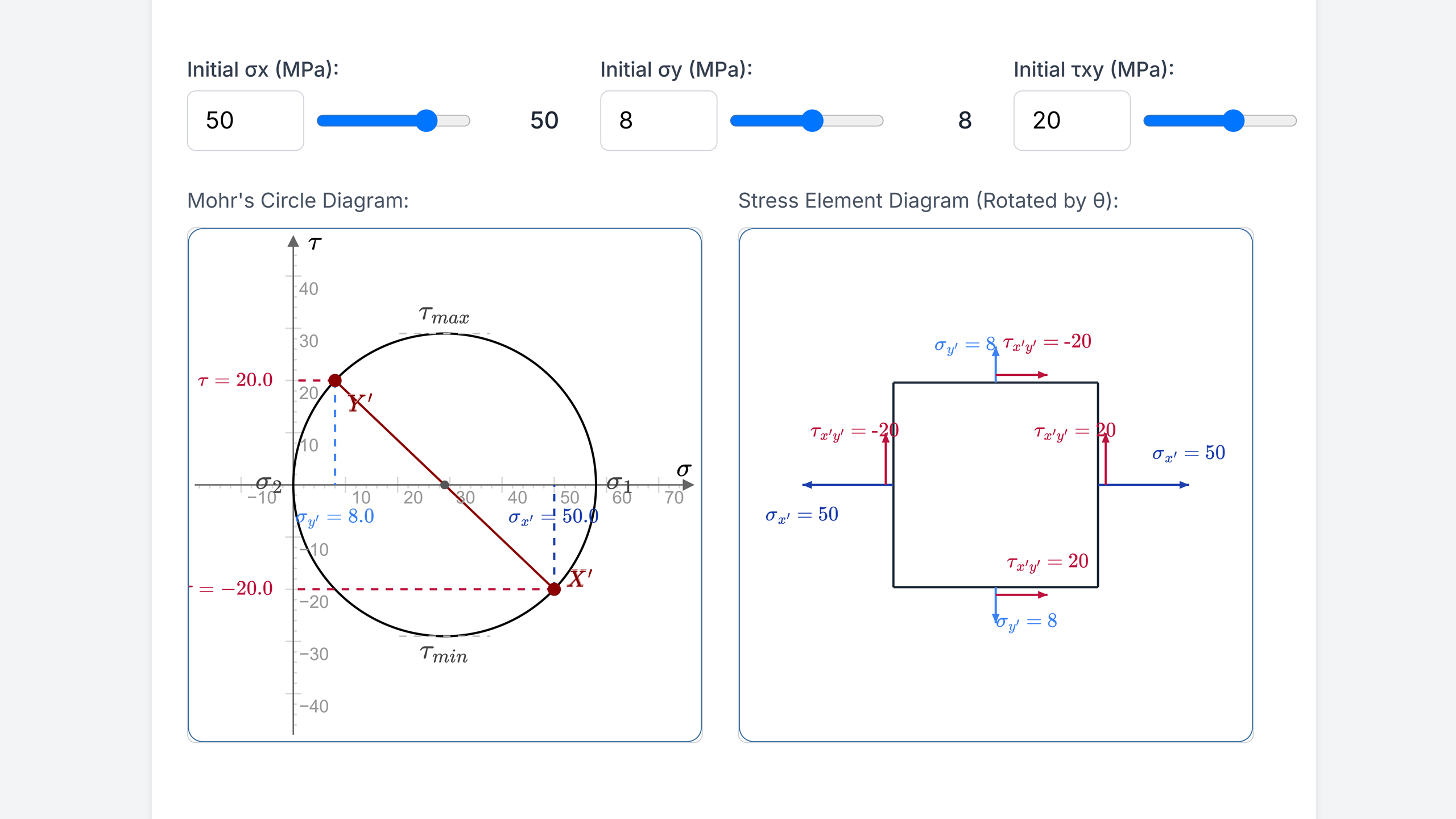
Reading about Mohr’s Circle is a great start, but seeing it respond to changes in real-time truly solidifies understanding. I’ve developed an interactive web application where you can:
- Input your own values for plane stresses , and .
- Set an angle for the plane of interest.
- Instantly see Mohr’s Circle drawn, along with the rotated stress element and all calculated values including principal stresses and transformed stresses.
Experiment with different stress states and rotation angles to see how the circle and the stresses on the element change. It’s a fantastic way to learn stress analysis!
Give it a try and master the art of stress transformation with Mohr’s Circle! If you have any questions or feedback, feel free to reach out.